
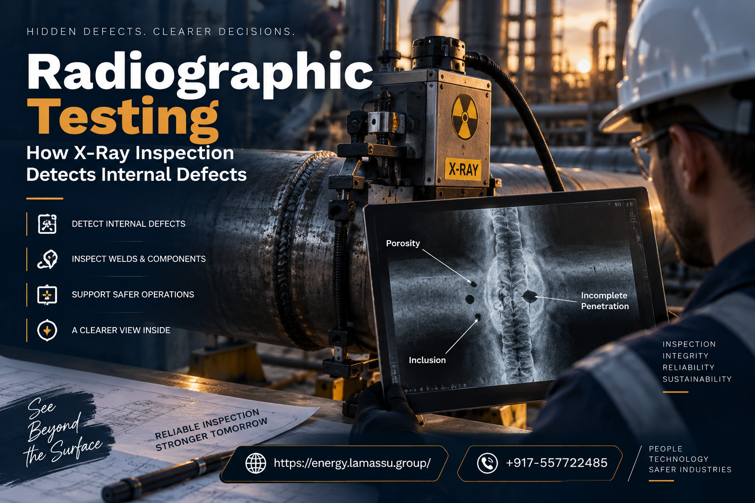
Learn how radiographic testing reveals hidden weld and material defects and what determines whether an internal defect can be detected.
What Is Radiographic Testing?
Radiographic Testing is a non destructive inspection technique that uses X-rays or gamma radiation to examine the internal condition of welds materials and industrial components without permanently damaging the inspected asset.
Radiation passes through the component and reaches a detector or imaging medium positioned on the opposite side. Differences in material thickness density and radiation absorption create variations in the resulting radiographic image.
Qualified personnel analyze these variations to identify indications that may represent internal discontinuities.
The main value of Radiographic Inspection is therefore not simply producing an image. It is providing information about internal conditions that may be difficult or impossible to identify through external visual examination.
What Problems Does Radiographic Testing Help Solve?
Industrial equipment may contain internal discontinuities even when the external surface appears normal.
Welding fabrication manufacturing and service-related conditions can create inspection concerns that require examination below the surface.
Radiographic Testing can help inspection teams investigate questions such as:
- Does a weld contain internal porosity?
- Are there voids or inclusions inside the material?
- Is incomplete penetration present in a welded joint?
- Does a casting contain internal cavities?
- Are internal density variations visible?
- Does a repaired weld require further evaluation?
The suitability of radiography depends on the specific inspection problem. It should not be selected simply because an internal examination is required.
How Does Radiographic Testing Work?
Radiographic Testing Methods rely on differences in how penetrating radiation passes through a component.
The inspection setup generally places an X-ray or gamma radiation source on one side of the component and an imaging system on the other.
As radiation passes through the material some energy is absorbed. The amount of radiation reaching the detector varies according to factors such as material thickness density and internal features.
These variations form the radiographic image.
A typical RT Testing process may involve:
- Defining the inspection objective
- Reviewing component material and geometry
- Selecting the appropriate radiographic technique
- Positioning the source and detector
- Establishing radiation safety controls
- Performing the exposure
- Verifying image quality
- Interpreting relevant indications
- Reporting the inspection results
- Evaluating findings against applicable requirements
This process highlights an important distinction: producing a radiographic image and determining component acceptability are not the same task.
What Defects Can Radiographic Testing Detect?
The ability to reveal internal defects is one of the main reasons Radiographic Testing is widely used for welds and industrial components.
Depending on the inspection conditions radiography can reveal indications associated with:
- Porosity
- Voids
- Slag inclusions
- Incomplete penetration
- Internal cavities
- Certain cracks
- Casting discontinuities
- Changes in material thickness or density
However radiography does not detect every defect equally well.
Why Are Some Internal Defects Easier to Detect Than Others?
This is one of the most important concepts when understanding Radiographic Inspection.
Radiography creates an image based primarily on differences in the amount of radiation reaching the detector.
A volumetric discontinuity such as a void or significant porosity can change the effective material thickness or density through which the radiation passes. This may produce a visible contrast difference on the image.
Very tight planar discontinuities can be more difficult.
A crack with an unfavorable orientation relative to the radiation beam may create only a small change in the radiation path and therefore may not produce sufficient image contrast.
Defect detectability can depend on:
- Defect dimensions
- Defect orientation
- Material thickness
- Material density
- Radiation energy
- Exposure geometry
- Image quality
- Detector characteristics
This is why the correct technical question is not simply whether X Ray Testing can detect cracks. The better question is whether the expected defect characteristics and inspection geometry make radiography suitable for detecting that specific condition.
What Defects Are Difficult to Detect with Radiographic Testing?
Certain discontinuities can be challenging when they do not create enough difference in radiation absorption.
Examples may include very tight cracks or planar discontinuities positioned unfavorably relative to the radiation beam.
Complex component geometry can also create overlapping features that make interpretation more difficult.
This limitation is important when choosing between different NDT techniques. If the expected defect is not well suited to radiographic detection another inspection method may provide more useful information.
X Ray Testing and Gamma Radiography
Industrial Radiography can use X-rays or gamma radiation. Both can produce images of internal conditions but the source characteristics differ.
X Ray Testing
X Ray Testing uses electrically generated X-rays.
The radiation can be switched on for the examination and switched off afterward. Depending on the equipment X-ray systems can also provide control over exposure parameters.
Suitability depends on component thickness material access and the capabilities of the available equipment.
Gamma Radiography
Gamma radiography uses radiation emitted by radioactive isotopes.
The relatively compact source arrangement can make gamma radiography useful for certain field applications.
However a radioactive source cannot simply be switched off. Handling transportation storage security and radiation protection therefore require strict controls.
Choosing between X-ray and gamma radiography should be based on the actual inspection conditions rather than assuming one source is universally superior.
Main Radiographic Testing Methods
Different Radiographic Testing Methods can be used to capture inspection information.
Film Radiography
Traditional film radiography records the exposure on radiographic film.
After processing the film provides an image that can be interpreted and retained according to project requirements.
Image quality depends on correct exposure geometry film selection processing and other inspection variables.
Computed Radiography
Computed radiography uses reusable imaging plates that are exposed and then scanned to produce a digital image.
Digital storage can simplify documentation review and image management.
The technology does not eliminate the need for correct exposure and image quality verification.
Digital Radiography
Digital radiography uses electronic detectors to capture inspection information.
Images can become available relatively quickly and can be reviewed and stored electronically.
The effectiveness of the examination still depends on suitable equipment technique geometry image quality and qualified interpretation.
Why Is Radiographic Testing Used for Weld Inspection?
Welds can contain internal discontinuities that are not visible from the surface.
Radiographic Testing provides an image of variations through the weld and surrounding material which can make it particularly useful for detecting selected volumetric discontinuities.
Common weld-related indications can include:
- Porosity
- Slag inclusions
- Incomplete penetration
- Internal cavities
- Certain other discontinuities depending on orientation
A reliable weld examination should consider material thickness joint configuration expected discontinuity radiation direction and applicable inspection requirements.
An indication should then be evaluated against the relevant acceptance criteria rather than automatically classifying every visible feature as a failed weld.
Radiographic Inspection for Piping and Pipelines
Industrial piping and pipelines contain welded joints where internal quality may need to be evaluated during construction fabrication repair or selected integrity activities.
Radiographic Inspection can be useful when the objective is to obtain an image of internal weld conditions.
However field conditions matter.
Pipe diameter wall thickness access configuration nearby personnel and operating activities can all influence whether radiography is practical.
Radiation exclusion areas are particularly important because they may affect other work occurring around the inspection location.
Industrial Radiography for Pressure Equipment
Pressure vessels and other fabricated pressure-related equipment may contain welds requiring internal examination.
Industrial Radiography can provide information about selected internal weld conditions without destructive sampling.
Inspection results should be considered alongside relevant fabrication records previous findings operating history and engineering requirements when a wider assessment is needed.
This prevents a single radiographic image from being treated as a complete equipment integrity assessment.
Radiographic Testing in Power Generation
Power generation facilities contain piping welded joints pressure-related components and fabricated equipment that may require internal inspection.
RT Testing may be considered for selected construction welds repair welds piping joints and other accessible components where radiographic imaging addresses the inspection objective.
It should not automatically be specified for every power plant component.
When the requirement extends beyond a single radiographic examination Lamassu Energy’s Power Plant Inspection service supports broader inspection requirements across power generation facilities.
Radiographic Testing in Oil and Gas Facilities
Oil and gas facilities contain extensive networks of process piping pipelines pressure systems and welded equipment.
Radiographic Testing can support selected inspection requirements where internal imaging is valuable.
The decision to use RT should consider:
- Expected defect type
- Weld configuration
- Material thickness
- Equipment access
- Operating conditions
- Radiation safety restrictions
- Applicable inspection procedures
This problem-based approach is more useful than specifying radiography for every weld simply because it is a familiar inspection method.
Radiographic Inspection in Middle Eastern Industrial Facilities
Facilities across the UAE Iraq Jordan Syria Saudi Arabia and other Middle Eastern markets can present challenging inspection environments.
High ambient temperatures remote locations restricted access continuous operations and simultaneous site activities may influence inspection planning.
For Industrial Radiography these conditions are particularly relevant because radiation exposure areas need to be controlled effectively.
Planning may need to consider nearby personnel operating equipment contractor activities site access work schedules and local radiation protection requirements.
The inspection technique should nevertheless be selected according to the equipment problem rather than geography alone.
Why Radiation Safety Is Essential During RT Testing
RT Testing involves ionizing radiation and therefore requires strict radiation protection measures.
Industrial radiography should only be performed by appropriately qualified and authorized personnel under applicable procedures and regulatory requirements.
Depending on the project controls may include:
- Controlled areas
- Barriers and warning systems
- Radiation monitoring
- Exposure planning
- Personnel dosimetry where required
- Secure source handling
- Prevention of unauthorized access
These requirements can influence whether radiography is practical in a busy operating facility.
Radiation safety is therefore part of method selection and not an issue to consider only after RT has already been chosen.
What Determines Radiographic Image Quality?
A radiographic examination is useful only when the resulting image provides sufficient information for the inspection objective.
Several factors influence image quality.
Radiation Energy
The selected energy should be appropriate for the material and thickness.
Exposure Geometry
Source position distance and component arrangement can influence sharpness magnification and distortion.
Exposure Conditions
Incorrect exposure can reduce useful image contrast or detail.
Detector or Film
The selected imaging medium affects how radiographic information is recorded.
Material Thickness
Increasing thickness can require different exposure conditions or equipment.
Scatter Radiation
Scattered radiation can reduce image contrast.
Component Geometry
Complex geometry may cause overlapping features that make interpretation more difficult.
Image quality should therefore be verified before relying on indications for technical decisions.
Advantages of Radiographic Testing
When matched correctly to the inspection problem Radiographic Testing offers several useful capabilities.
Internal Imaging
The technique can reveal selected conditions inside materials and welds without destructive examination.
Permanent Inspection Record
Film or digital radiographic images can provide a record for documentation and later review.
Detection of Volumetric Discontinuities
Radiography can be particularly effective for selected volumetric defects such as porosity and voids.
Weld Examination
The technique is established for many industrial weld inspection applications.
Digital Inspection Options
Computed and digital radiography can support electronic image review storage and reporting.
These benefits should always be considered alongside the technique’s limitations.
Limitations of Radiographic Testing
Understanding where radiography may be less effective prevents the wrong inspection method from being selected.
Important limitations include:
- Ionizing radiation safety requirements
- Controlled-area requirements
- Access and positioning constraints
- Reduced sensitivity to some unfavorably oriented planar defects
- Challenges with complex geometry
- Potential operational disruption
- Equipment or source requirements for thick materials
- Dependence on qualified image interpretation
The most suitable inspection technique is therefore the one that best addresses the expected defect and component conditions rather than the method with the longest list of advantages.
Radiographic Testing vs Ultrasonic Testing
Radiography and ultrasonic inspection can both investigate internal conditions but they do so using different physical principles.
Radiographic Testing creates an image using penetrating radiation while ultrasonic inspection evaluates the behavior of high frequency sound waves within a material.
Radiography can be particularly useful for selected volumetric discontinuities and situations where an image record is valuable.
Ultrasonic techniques may offer advantages for selected planar discontinuities thickness measurements and applications where one-sided access is important.
Method selection can depend on:
- Expected defect
- Defect orientation
- Material
- Thickness
- Geometry
- Accessibility
- Radiation restrictions
- Inspection requirements
Neither method should be described as universally better.
For a detailed explanation of ultrasonic inspection see our Ultrasonic Testing guide while this article remains focused specifically on radiographic detection of internal defects.
When Should Radiographic Testing Be Selected?
The decision should start with the expected inspection problem.
Radiographic Testing may be suitable when internal imaging is required certain volumetric discontinuities are expected weld internal quality needs assessment or a radiographic record is valuable.
Before selecting RT inspection teams should ask:
- What defect are we trying to detect?
- Is its expected orientation suitable for radiography?
- Can the source and detector be positioned correctly?
- Is the material thickness suitable for the available technique?
- Can radiation controls be established safely?
- Does the applicable procedure permit or require the method?
If these conditions are not satisfied another NDT technique may provide more useful information.
For inspection requirements involving multiple techniques Lamassu Energy provides Non Destructive Testing services for industrial and power generation applications.
From Radiographic Inspection to an Equipment Decision
The purpose of Radiographic Inspection is to provide useful inspection evidence rather than simply generate images.
A strong decision process is:
Equipment Concern → Inspection Objective → RT Technique → Image Quality Verification → Interpretation → Engineering Evaluation → Appropriate Action
The resulting action might involve acceptance additional examination repair monitoring or further technical assessment depending on applicable requirements.
This distinction also prevents two common mistakes: assuming every radiographic indication represents failure and assuming an image without visible indications proves that every possible defect is absent.
When inspection findings require field-level technical coordination Lamassu Energy’s Technical Field Advisor service can support technical activities around critical industrial and power generation equipment.
Common Radiographic Testing Mistakes
Selecting RT Before Defining the Defect
The expected defect should influence the inspection method rather than choosing radiography first and defining the objective afterward.
Ignoring Defect Orientation
Some planar defects may produce limited radiographic contrast when their orientation is unfavorable.
Poor Exposure Planning
Incorrect geometry or exposure conditions can reduce image usefulness.
Treating Every Indication as a Failure
Relevant indications require interpretation and evaluation against applicable criteria.
Ignoring Radiation Exclusion Requirements
Inspection planning must consider nearby personnel and simultaneous site activities.
Assuming a Clear Image Means No Defects Exist
Every NDT method has detection limitations. Radiography cannot prove the absence of every possible discontinuity.
Why Qualified Radiographic Testing Personnel Matter
Reliable Industrial Radiography requires both technical inspection competence and strict attention to radiation protection.
Personnel involved in the work may need competence in:
- Radiographic principles
- Exposure techniques
- Image quality evaluation
- Component geometry
- Indication interpretation
- Radiation protection
- Applicable procedures
- Inspection reporting
Qualified personnel become particularly important when findings influence weld acceptance repair decisions or further engineering evaluation.
For projects requiring coordinated onsite field personnel Lamassu Energy provides Dedicated Service Crews for industrial and power generation environments.
Radiographic Testing Support from Lamassu Energy
Effective Radiographic Testing requires more than access to an X-ray or gamma source. The inspection objective technique field conditions image quality safety requirements and interpretation all need to work together.
Lamassu Energy supports power generation oil and gas and industrial organizations with inspection technical field and equipment-focused solutions for demanding operating environments.
Through its Non Destructive Testing services Lamassu Energy supports facilities requiring professional assessment of welds materials and critical industrial equipment.
Combined with power plant inspection technical field advisory and dedicated field crews this approach helps connect inspection findings with wider reliability maintenance and operational requirements without treating the radiographic image as an isolated result.
Frequently Asked Questions About Radiographic Testing
What is Radiographic Testing?
Radiographic Testing is a non destructive inspection method that uses X-rays or gamma radiation to produce images of internal conditions within materials welds and industrial components.
What is RT Testing?
RT Testing is the common abbreviation for Radiographic Testing and refers to the use of penetrating radiation for industrial inspection.
What defects can Radiographic Testing detect?
Radiography can reveal selected internal discontinuities including porosity voids slag inclusions incomplete penetration internal cavities and certain cracks depending on inspection conditions.
What defects are difficult to detect with Radiographic Testing?
Very tight planar discontinuities and cracks with unfavorable orientations relative to the radiation beam may be more difficult to detect.
What is X Ray Testing used for?
X Ray Testing can be used for selected welds castings piping fabricated components and other industrial equipment requiring internal imaging.
What is Industrial Radiography?
Industrial Radiography uses X-rays or gamma radiation to inspect the internal condition of materials and components without destructive examination.
Why is Radiographic Testing used for welds?
It can reveal selected internal weld discontinuities and provides a radiographic image that can be evaluated and retained as an inspection record.
Can Radiographic Testing detect cracks?
Certain cracks can be detected but visibility depends on their dimensions orientation material thickness exposure geometry and image quality.
What is the difference between X-ray and gamma radiography?
X-rays are generated electrically while gamma radiography uses radioactive isotopes. Selection depends on equipment component thickness access and site conditions.
Is Radiographic Testing better than Ultrasonic Testing?
Neither is universally better. The appropriate method depends on defect characteristics material geometry accessibility inspection requirements and radiation restrictions.
Is Industrial Radiography safe?
It can be performed safely when appropriately qualified personnel apply the required radiation protection procedures controls and applicable regulations.
Does Radiographic Testing damage equipment?
No. NDT Radiography is designed to examine components without the destructive sampling associated with destructive testing.